Hacking my Wireless Doorbell
Making a 433MHz Doorbell Speak 2.4GHz

I wanted a doorbell that I could integrate with my Home Assistant setup over WiFi. I found a cheap the cheapest 433MHz doorbell on Amazon and away I went.
The doorbell in question is a stechro that I got for ~£8 delivered. It seems to be a relabelled KERUI M523. It takes a user-replaceable CR2032, and it works! Time will tell if it's waterproof.
Attempt 1
My first thought was to use an XY-MK-5V (also labelled MX-RM-5V, XD-RF-5V) 433MHz receiver board, and hook that up to the ESP8266. These boards do work, but they're definitively at the lower limit of what's functional. They consist of a minimal resonator circuit and op-amp, and often come with various passives missing 👀. They are however — again — very cheap.
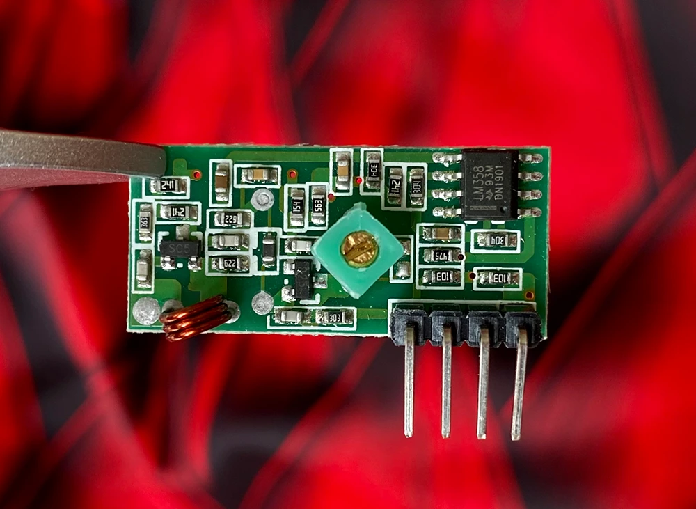
They don't come with any sort of antenna, and so in their naked state, have a range of a few centimetres.
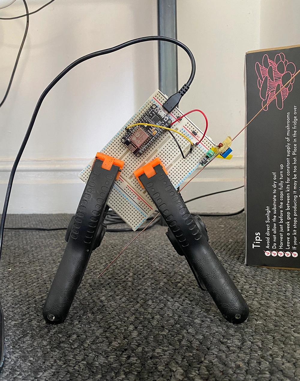
I fashioned a simple 1/4 wave antenna from some wire, and I tested it up to 10m, but the directionality was too high for reliable use with the doorbell. Pulling this off would have meant designing a custom enclosure with the ability to position the antenna accurately. So I changed tack.
The Receiver
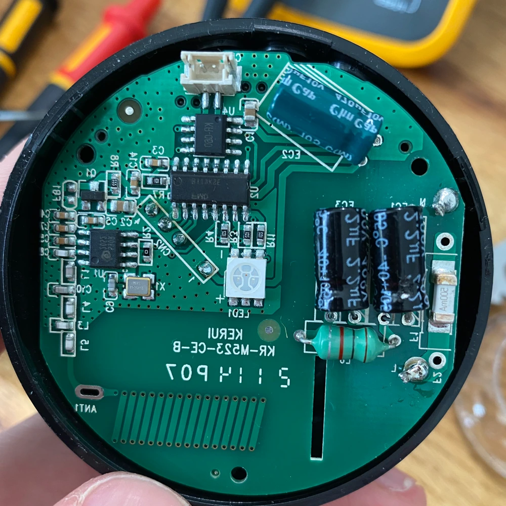
The receiver has a PCB antenna manufactured with much more precision than my hand-made copper wire job, and indeed the range of the doorbell when paired with its receiver was much much better, and had no issues with directionality. This being the case I planned to reuse the antenna.
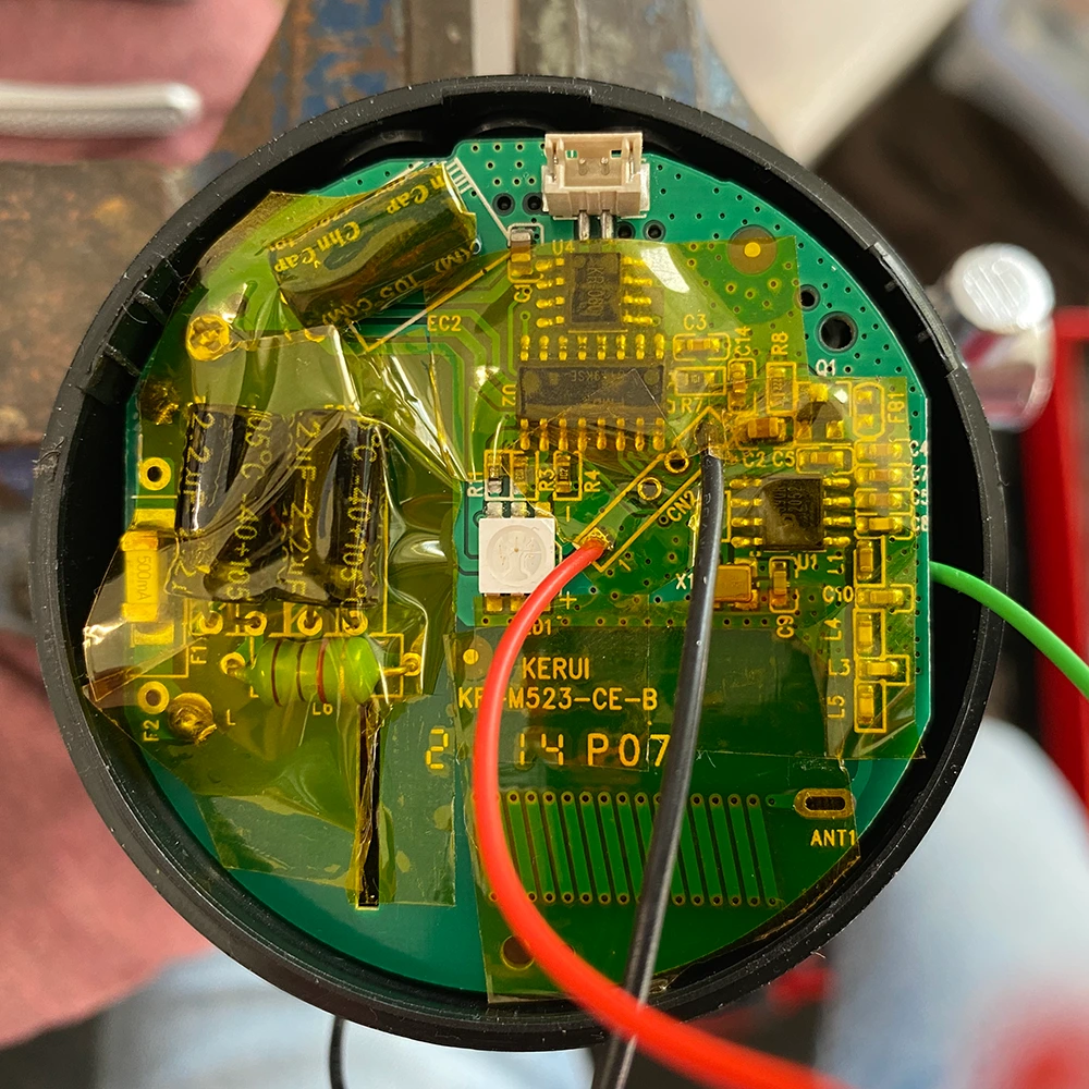
Opening it up, the receiver consists of a 5V power supply, the receiver circuitry with antenna, and a microcontroller to decode the signal, and play one of the various annoying tunes from its speaker.
Importantly, the board includes a SYN590R 433MHz ASK receiver IC from Synoxo. This replaces the XY-5V-MK, and has much better performance.
After probing around, I found the power rails, and the data output from the SYN590R all exposed, the latter on a test pad. This was really helpful, and meant that I could plug these straight into the ESP8266 without any additional circuitry1.
I decided to decode this output instead of listening for the receiver to 'chime' as this way, I'll be able to listen for more than one transmitter in the future, and respond to them individually.
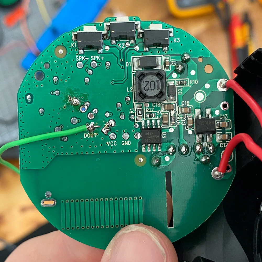
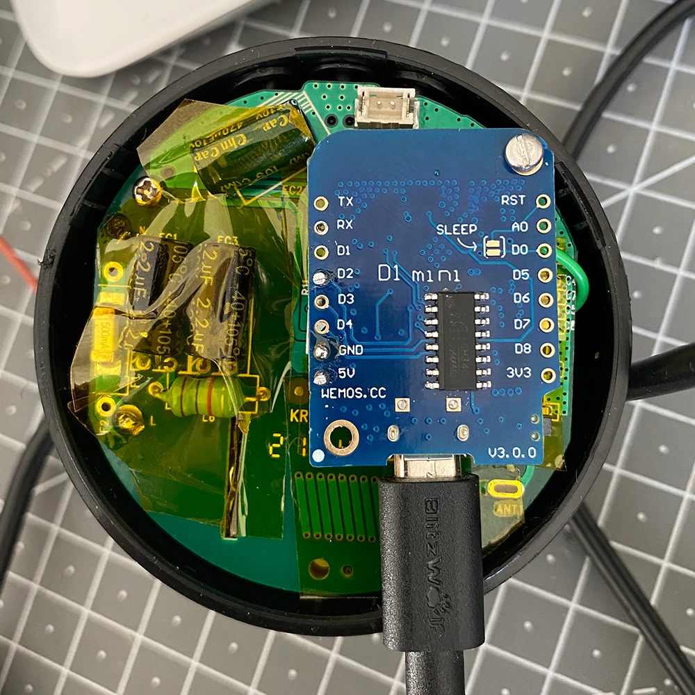
The receiver housing had enough room to fit a WEMOS D1 Mini, so I Kapton'd the original board and mounted the D1 Mini directly on top. This keeps everything in the original housing.
ESP8266
On the software side, I'm using the rc-switch library to decode the receiver output.
This is an amazing library that takes all the complexity out of decoding the signal and spits out the value transmitted together with the encoding.
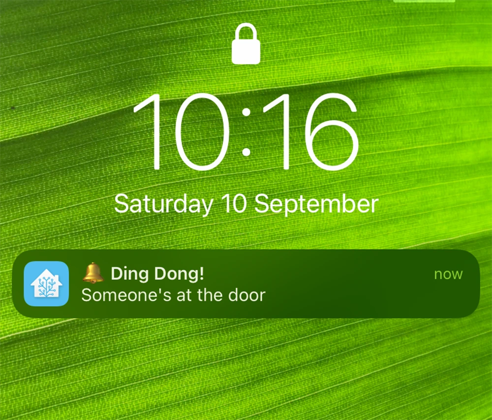
The decoded information is relayed over HTTP to a Home Assistant webhook, where the data transmitted is matched, and actioned appropriately.
...
#include <RCSwitch.h>
...
RCSwitch rc = RCSwitch();
void setupRadio() {
rc.enableReceive(D2);
}
void loopRadio() {
if (rc.available()) {
String json;
StaticJsonDocument<512> document;
document["decimal"] = rc.getReceivedValue();
document["length"] = rc.getReceivedBitlength();
document["delay"] = rc.getReceivedDelay();
document["protocol"] = rc.getReceivedProtocol();
// document["raw"] = rc.getReceivedRawdata();
serializeJson(document, json);
http.begin(client, configuration.triggerURL); //HTTP
http.addHeader("Content-Type", "application/json");
http.POST(json);
http.end();
rc.resetAvailable();
}
}
...
The same could be achieved with ESPHome, which is probably a better option.
Home Assistant
On receiving a doorbell event, I've used my node.js Home Assistant scripting platform2 to run some logic based on who's at home, who's asleep…etc, and then notify the appropriate people, who can accept or decline the door call, triggering further logic.
- The I/O on the
ESP8266is5Vtolerant. ↩ - possibly coming soon ↩